
Hi. This time, I wanted to write about understanding the LFE(Low Frequency Effects) and challenges I faced with the LFE channel in my initial days of mix and continued for some time until I figured out the reason. This is going to be a long post. But before that, let me give you a brief history of how I used to use it.
My Learning
My Initial days of mixing started with the concept that LFE was meant to have anything with Lows in it. Well, for a long time, I assumed that anything like the Kick or Bass would have to go that channel because, isn’t that the one for low frequencies? This was where my understanding of the way cinema sounds was limited, and as I learnt more, I felt it should be shared. The reason I say this is because even today, I see many beginners and engineers doing the same mistakes I used to make and not notice it.
The Difference and realization came one day as I was listening to a song in a movie I mixed while the Dolby Consultant was mastering it. Suddenly I felt that the low ends of the song didn’t sound right. For a while I thought it was my ears that were tricking me because of ear fatigue. (I had been working very long and I was an associate mix engineer then). I turned to my friend and Dolby consultant Bharat and asked him if he felt the song lacked any bass. Now, this is what’s good about having friends who are also consultants. They don’t bullshit, and they can be straight as a needle. Needless to say, he was sensible and said it didn’t sound like my other mixes and assumed I tried a different route. After a moment of contemplating, which was about a second long, sure enough, we load up the session and check.
I played that back and as I was expecting, the lows were back in form. This puzzled me. But I have to admit 2 things here. I was an assistant to a good mix engineer who gave me the freedom to take responsibility of the mixes I did. I also was very eager to troubleshoot. But, still, it became very hard. Finally after a few minutes, we played the mastered portion and it lacked bass. Now, Bharat asked me to invert the phase in the LFE channel in my mix and listen. Sure enough, it sounded low in bass, but was exactly the way the 5.1 mastered version played. But, then, as an idea, we inverted the phase on the LFE channel and then mastered. It sounded the right way.
Here, was when I learnt 2 of the most important lessons that changed my mix and my approach to it.
- The Mastering Process has a low pass filter on the LFE
- Always listen with the encode option on the Dolby Unit while mixing. (Though this will induce a 2 frame delay with regards to video due to the encode-decode process on the dolby DMU, this can be offset on the video track in Pro Tools.)
But what took me a few more years was to understand the explanation behind it. That came from another very good friend and live sound engineer, Niranjan. The learning was about filters and the mystery behind it.
The Reason
In the earlier note, you would have seen how inverting the phase in the LFE channel made it work. This led to me thinking about what the role of phase was. The truth, when it hit me, was simple yet profound. The LFE is routed to the Sub Woofer. The mistake I was doing and we sometimes still do was this. We have a send to the LFE in Pro Tools and if it’s a kick or a bass track or anything that needs that extra oomph, we increase that send. Now, in today’s mixes, it is very rare to print master, as before since all formats are digital and there is no encode-decode process. (It was for print and honestly; the print format is no longer very prominent. We all saw the pain Quentin Tarantino had to go through for Hateful 8). Now, because there is no print master, we want to keep the LFE channel that we record to be clean and have only the low frequency. Again, we don’t want the higher frequencies from lets say an explosion or a stereo perc loop that has good bass to go into the LFE channel. So, what do we do? We insert a low pass filter. And to get the cleanest sound, we put the highest slope. This is where the issue happens. Why? Because filters introduce a phase and since the same signal is present in the main channel as well as the LFE (they are coherent), they will interfere. (Remember that we are sending from the main channel).
Take a look at the video below to understand the above note. There is no audio to be heard, but you can instantly see what is happening.
This is the routing: 7.1 Center channel and the LFE are combined into a mono bus with 2 separate Auxes so that the Pan law doesn’t affect the signal displayed. (Pan law causes the signal to drop by -3dB or what is set in the session setup-Pan depth section.) This Mono bus is then shown on a Mono Aux to monitor. (It’s also to simulate the phasing issue. Else, we won’t be able to visualize it.) This Mono channel will represent exactly what happens in the real world when the LFE interacts with the Center channel in this case. I will be using a 120Hz sine wave for purposes of demonstration, though things are a little different with complex waveforms. Watch what happens when the LFE send becomes +3 dB.
How can we overcome this? From my understanding, there are 2 ways. (Please feel free to comment if you find additional techniques.)
- Have a separate design track for LFE
- Understand Filters.
I think we all have the first part sometimes. But, it is very useful to understand filters and their secret role in our daily life. My knowledge of filters isn’t very deep; yet, it is something that I did spend sometime trying to understand. Not from a software / electrical design point of view, but from a mixing point of view. This will change the way you will look at EQ and filters. To understand filters, we need to understand a few other things first.
Phase
What is phase? Phase is simply the difference in time vs. amplitude between two sinewave sources. This is the technical definition. But, here are the two keywords we need to keep in mind.Phase is simply the difference in time vs. amplitude between two sinewave sources. One thing that I didn’t understand was, if it was the difference in time, why was it measured in degrees? To quickly realize that, look at the figure below.

Phase Cycle
We all know that the waveform is amplitude on a time scale. But, it can be represented like a circle too as above. You will notice that if the circle moves ahead, then, the waveform will shift, like a time delay. But, the interesting part is, no matter what the radius of the circle is, whether the circle is big or small, the angle will always be at that same point on the circle, ie, 90 degrees, 180 degrees, etc will be on the same point on the circle, but different on the time scale. This means that the frequency can be entirely different. Yet the degree doesn’t change, even though the time for that will change. This led me to understand that Phase has no meaning without the frequency it is associated with. But how is this useful to us? Well, before I go into the LFE explanation, let me try it with a simple recording technique that some of us are familiar with.
If we have miked a snare on top and bottom, experience would tell us to invert the phase on the mic below because the pressure on the diaphragm of the bottom mic will be the mirror image of that on the top. But that’s not what I was getting at.
Calculating Phase
Phase can be calculated as:
Phase angle (deg) φ = time delay Δ t × frequency f × 360
Don’t get worried about the formula. I will use the above snare example to explain some stuff.
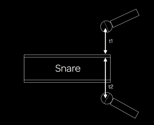
Snare Miking
Now, notice that there are two mics on the top and the bottom, and the time of arrival towards the top and bottom is t1 and t2 respectively. This means the difference in time is t2-t1, which is our time delay, or Δ t. Now for ease of calculation, lets take that t2-t1=4ms (4/1000 second). (I know that may not be the case in real world, but lets assume so for now).
We all know that cancellation occurs at 180 degrees. So, if we put 180 in the equation above then
180 = (4/1000)Seconds x f x 360
This gives us the cancellation frequency as
f = 180 / (.004 x 360)
f = 125 Hz.
This is where the first cancellation occurs. Wait, what? First Cancellation? Yes. There will be harmonics that will cancel too. How? Well you remember the degrees were represented as a cycle in the first Figure? That means after one complete turn (360 degrees), the point of 180 degrees will reappear. This means the next point of cancellation is 180+360 = 540 degrees.
If you put this in the above equation, you will get f = 375 Hz.
Is there a pattern? Yes. If you look at the initial time delay, that was t2 – t1 = 4ms. Now, the fundamental frequency that has a time of 4ms (.004 seconds) is
1/(.004) = 250 Hz.
If you look at the values of cancellation we got, they are at 125, 375, etc etc. This is 0.5×250, 1.5×250 etc. So, the rule is
Cancellation will occur at 0.5 fundamental frequency, 1.5 fundamental frequency, 2.5 fundamental frequency etc while addition will occur at 1x, 2x, 3x the fundamental frequency.
An interesting application of this while recording witih multiple mics, is if you know the tone you are looking for, adjusting the mic distance will help you get that. Ofcourse some of the lower frequency will require that you have the mic at outrageous distance. Well, a quick way would be to get to the closest cancellation length, and then invert that mic. Anyways, recording wasn’t my strong point, so I will get back to the LFE, but I hope you understood how phase degree relates to time.
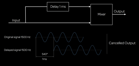
In a mixing scenario, the same will occur if you take a signal of say 1500 Hz and delay it by 1 ms and add it back to the main signal. Here, 1ms is a phase shift of 540 degrees for 1500 Hz. This means it will perfectly cancel. So, adding delay times and using creative delays also can cause a change in the tonality. (This can also help create interesting sound design by adding multiple delay times to a vocal and summing it back. Like a phaser but with much more control on the frequencies you want to manipulate, now that we know the math! Adding this signal to a reverb or a stereo delay and blending it with some of the other methods I have suggested in the other blog posts and well, now that’s a ton! On a separate note, if you wanted a brick wall filter, then using the same principles, the delay needed for the signal to arrive because of the phase would probably be months!)
Delay for Cancellation
Is the Phase always cancelling? No. It adds at different values too. Here is a phase template that plots these changes and will be handy to have as a reference.

Phase Cycle
Interesting Note: Why is this useful in DSP? Phase. To work on a frequency, the sample rate has to be twice of that. (Nyquist Throrem). For DSP, it must finish all computations during the sampling period so it will be ready to process the next data sample. The maximum time taken for an algorithm instruction execution gives the max frequency upto which it can sample. (Freq = Cycle / Time). So, using this, theoretically the HDX chip has less than 2μs to execute an algorithm at 192 kHz and this is where math optimization for plugins plays an important role. My knowledge of DSP is too poor to go into much more detail. But I assume a similar math is also what causes different audio engines on the native side of things to sound differently between different DAWs. It would be interesting to read more on that at some point.
What is a Filter
A filter is a frequency dependent amplifier circuit. It can exist as Low Pass, High Pass, Band Pass and Band Stop as in the figure below.
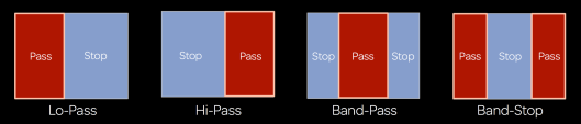
Types of Filters
But, based on other parameters, there are different kinds of filters too. One common example is the Butterworth filter. It’s a 6dB per octave filter and has 3dB drop at cut off frequency.
This is again very important to know. If you put a 6dB per octave at 120 Hz for example, it means that 120 Hz will drop by 3dB on the output. My initial understanding was 120 Hz would be the same level and 240 would drop by 6dB as that was an octave more. But as I read, I understood better. This also explains why in the video above, the signal cancelled completely at a send level of +3dB.
As Slope increases, it means the order increases. So, 12 dB/ Octave is 2nd order etc. It has 45 degree Phase shift per order. This is also interesting. How are these filters actually working in the real world without plugins? Well, filters are constructed as shown in the diagram below.
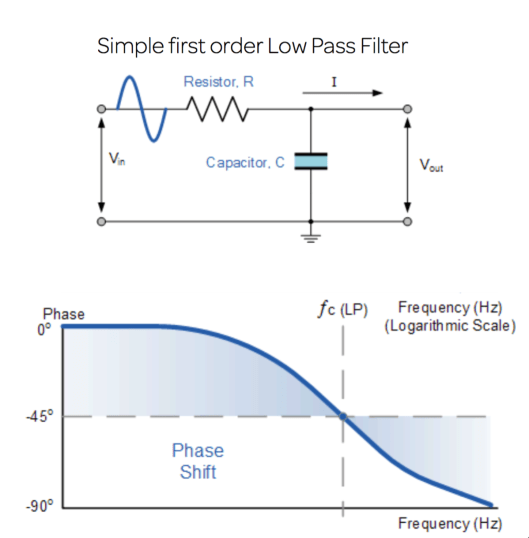
Simple Low Pass Filter. Image Courtesy Google. Apologies as I can’t find the source.
The capacitor is what acts as the actual filter. As the Frequency is increased, the capacitor charges and discharges. The capacitor is more susceptible to low frequencies to charge and discharge. This is called capacitive reactance. It is how the resistance of a capacitor changes with regards to the frequency of signal passing through it. (Basically, if I were a capacitor and I have to stop one person per minute at a gate, easy peasy. But if it’s an opening for a metallica concert and I am the only one there, well, what can I say? Get it? Is gatecrashing close to a capacitive filter?!? 😀 ). What happens is when the frequency increases, the charging and discharging time decreases and after a point, it will cause the signal to pass through the capacitor, acting as a short circuit. Look at the above figure, and you will see that Vout will become 0 because above a certain frequency the entire signal will pass through the capacitor to the ground. Now, charging and discharging takes time and causes delay. And as we all know this time delay in relation to the frequency will cause a phase shift. This is how filters cause phase shifts.
I haven’t gone to the Linkwitz-Riley and others because they are a bit more complex to explain. But, the Linkwitz-Riley is a combination of butterworth filters and the Pro Multiband uses an 8th order Linkwitz-Riley where the crossover phase is 360 degrees or 0 phase cancellation. This is quite amazing as no matter how you adjust the bands, there wont be issues in the phase. This is also the reason why this plugin can’t be used in parallel compression. Yet, if you use the Avid Pro Multiband splitter, rest assured that the signals will sum to 0 phase at the split.
But we were talking LFE
Yes. Here, is where the filter I mentioned in the first post makes sense. If that filter is at a frequency that is at a fundamental note of the bass or kick etc, that will begin to cancel with the signal from the main speakers. The easiest way to circumvent that, and my go to weapon is the Pro Subharmonic from Avid. The logical reason is this:
- It generates waveforms based on the input signal.
- It gives you access to the gain of Half the input signals, eg at a range of 60 and 90 as shown in the figure, it gives control at 30 and 45 hz. This also means that it is somehow generating half waveforms, thereby constructing true harmonics that would make sense in the program.
- It cannot cancel with the main signal, as for signals to cancel, they need to be coherent. Since this is generating signals, there is no way the LFE will have exact signals as the main channels.
There are others out there like the LoAir, Aphex Big bottom, and the hardware DBX 120A etc. For some reason, I like the way Pro Subharmonic works in the lower frequency region and also it works from Mono all the way to 7.1 and is AAX-DSP too. Understanding these things helped me with the way I started looking at filters and the LFE in a different light and also choosing what I had to send to the LFE and the very important question of IF I need to send at all. Not just that, remember, EQs are in a way filters too. So, they too have a similar way of working. But that’s probably for a different post. For now, let’s break it down with LFE!
-FM

Hey Sreejesh,
First let me say thank you for such in depth blogs. Your knowledge is so deep on the issues you talk about. Its so refreshing to read things laid out so succinctly. So after reading your post I decided to duplicate your experiment in order to absorb the concept more clearly. I ran into a couple of things I wasn’t expecting. I’m sure you’re busy and might not have time to investigate but hopefully you’ll have some insight. So here is what I came up with.
I have two rigs. A new mac trashcan with a 5.1 setup and a portable macbook pro for location gigs. Both are running PT 12.4.
I noticed two things when trying this experiment.
I first tried on my mac trashcan. I wast getting the Phase track in your example to completely null out so out of curiosity I switched the EQ1 plug in from DSP to Native there was a jump of +0.6 db (on the level of the phase track) while the plug in was in bypass and no delay compensation selected.
EQ1 in bypass in DSP mode: Phase check track pk level at – 12.4
EQ1 in bypass in Native mode: Phase check track pk level at -13.0
put it back in DSP mode so it would match the -12.4 example, turned off bypass and set the eq as in example. Phase check track was NOT 180 degrees out of phase with center channel. It was at -36.7. A drop of -24.3 db. The phase track does cancel considerably and when you invert the phase on the eq it goes back to -14.0 not -12.4. I tried with the EQ in Native mode and had a similar outcome. Neither completely nulling the phase track. I also tried this same thing with Avid EQ3 7 band and got the same results. No null.
I took the exact same session. Copied it over to my laptop, opened it up and the phase canceled exactly as in your video example with all the same levels. Identical I/O.
So two issues.
1. why would switching from DSP to Native on an EQ while in bypass change the level? Every plug in I tried that was DCP and Native yielded the same results. I’ve never experienced this ever before. I’m assuming it has something to do with the nature of the experiment and the summing (?) Changing buffer size didn’t change anything. And delay compensation was always off for the test (although neither of these things should really have any affect on the test).
2. why would the exact same session yield different results on two different machines?
I never would have expected any of this to come up. I was just trying to duplicate the session to fully wrap my head around your blog post. I do have screenshots of all the different results. If you could offer any input on this that would be greatly appreciated. I do also have another entirely different question after all this about properly down mixing the LFE into a stereo stem. But one thing at a time.
Thank you. chris
That seems to be very interesting! Let me try it out and figure why. Never happened on my end before or I may not have noticed. But I will try and check that. Thanks a lot for reading my blog with so much interest!
Of course. Thanks for getting back so quickly. I did have another quick (well maybe) question for you. Is there technically anyway to add the LFE into the stereo down mix or will there always be phase issues. This was my real question! Everything I’ve tried seems to produce mixed “phasey” results. I know most things I read so don’t include it at all but I’m curious if it’s possible or in the end, just not necessary. I’m somewhat new to 5.1 mixing so please forgive me if this question is a bit basic. Thanks chris
Hi Chris. No not a basic question at all! In fact something that haunted me for a long time. There are a few things I understood while doing downmixes and making mistakes.
The phase issue may occur when the LFE was created by a send from one of the main tracks while mixing as in the example above. In such cases there is no real reason to include that track as the main track will be full range anyways and the additional extention is not required as the LFE plays no role as an addition in stereo.
But, there are 2 scenarios where the LFE plays a role in downmixes. One is of the LFE has a subharmonic processing, and the other is if there are specific tracks cut for the LFE. Effects like designs or guns, blasts or sometimes music may have that added element which is not present in the main channels. These may need to be blended in. In such cases, they won’t usually cancel because they are not coherent waves.
What I have been doing and it makes things sound a lot better is to ride the LFE levels based on situations where it will benefit the main mix. Now this is what I finally do after a lot of experiments and listening (and of course mistakes! No problem being honest here!). While this does take a lot more time especially in film, I believe it’s worth it because it’s that stereo that will be played more than anything in the long run of the movie if it’s a hit.
Regarding the other one, only thing I can think of is of the engine changes in the two systems between dsp and native is bringing a summing difference. (There is no heat or anything active is there?) But I can check that at some point at my end to confirm. 🙂
So to address the hardware situation, Heat was on but not activated. I’m not at my trashcan rig to check out what happens when I take it fully off but I did try it on my laptop and even if Heat is fully on the phase channel still nulls. Regarding the LFE question, I still have a few questions if you have time to go down this hole with me. I have my LFE send coming from it’s own aux’s being feed by sends from individual tracks. Is that an incorrect way to create the LFE? Regarding coherent waves, have you ever experimented with a hard slope on tracks being sent to the LFE and the sub harmonic generator so make sure no shared sub goes to main mix? Is that something that would prevent phasing on the down mix or is that just compromising the sound too much at that point? I hope I’m making sense.
Hi Chris. The send way isn’t wrong at all and in fact was a way to do it on some of the large format consoles that don’t have a dedicated LFE send. The Avid Euphonix S5 does have it though. When you say hard slope does that mean mean a filter on the LFE channel? The Pro subharmonic has those filters in place and so I dont use another filter in the path. If you look at the above having multiple filters is like creating the additional phase shifts. The honest truth is not all situations are bad. If you don’t notice the drop then probably the fundamental frequency isn’t getting affected. But using the harmonic generator should also be done to taste. The good part about this is the wet dry part where you can still decide how much to generate thereby not compromising the sound.
Hi Sreejesh,
Ok, that’s good to know that I’m going down the correct path as far as my LFE routing goes. I do use the Avid Sub harmonic as well and I do use the filter and the dry/ wet. I guess I was just reaching with the extra filter comment! The reason this really came up is because I think that a lot of people these days that have home systems that have stereo speakers and a sub. If so then it would be nice to be able to fold in any LFE information into the stereo mix. I understand what you are saying about non coherent waves and I’ll have to try a few more experiments with folding it into the stereo to see what I come up with. This leads to another question of bass management. In my setup I have bass management set at 80Hz. Do you use some sort of bass management or is it something that is just not done? I know bass management can be a taste thing but would it possibly be better to not have it on so I can accurately hear how much low end is coming out the 5.0? And just to clarify I work mostly in television and not film and I know you are a film mixer but this overall technical conversation is extremely helpful. Thank you again.
Hi Chris. In a film space, usually bass management isnt something that is used. Its because there is usually designed sounds for the LFE and that is treated separately as I mentioned in the posts above. But when it comes to home theaters, many players do Bass Management and its usually around 80. If its a subwoofer, my understanding is its 120 Hz. If I am not wrong, many TV productions now mix as a regular 5.1 but with comparatively lesser info in the LFE channel. And for music, my philosophy for the most part has been to make it work in the main channels and then see if the LFE adds to it. If the mix cannot survive without the LFE, then I probably have more work to do!
Right. That all makes sense. I’m going to loose the bass management but check mixes from time to time with it in. Thanks again for all the info and I’m sure I’ll be writing back soon.
Hi Sreejesh,
a big thank you for sharing all your experience and knowledge with us. I have learned so much after following your posts.
Regarding this LFE, I have a few quick question. To make it simple, what you are trying to say here is that, because 5.1/7.1 has already 5/7 full-range main channels, it would be redundant if we send the same low frequencies directly from the main channels as it will introduce phase issue (unless it is specific cuts specially for LFE channel) am I right? Which is why instead of sending the same low frequency to LFE, you suggested to use sub-harmonic processor such as Avid Pro-Subharmonic plugin. But may I ask where do you suggest to insert that subharmonic plugin, in the channel itself, or in a LFE aux bus?
Not really. What I was trying to get across was the issue of why the LFE can induce phase when there is a filter in place. The reason we send LFE is to augment and highlight the lows. And using the sub harmonic plug in works to create non coherent waves. I usually insert this on an LFE sub path master so that I can control the overall input to the plugin and make sure it isn’t distorted as on a master the plugin is post fader.
Hi Sreejesh,
Thanks for the post. I was wondering if you used a linear phase EQ to do the highpass – wouldn’t this solve the problem?
Wouldn’t it introduce delay?
Pingback: Arctic: History telling trough sound design – João Pereira
There is actually a much simpler way to deal with phase cancellation: just delay the main channels. There is an interesting AES paper about filtering the LFE with a scheme and corresponing order slopes/delay times in ms to apply.
Sure. But then when you’re mixing to a reference picture that isn’t too practical to do I guess. 😊
Well, it’s actually the simplest way. Just decide a filter slope and apply a delay to the main channels according to the AES paper. Moreover the slope for the LFE is usually way steeper than 24db/octave: If you consider the Waves LFE 360 plugin, for instance, the filter for the Dolby specification is a 60db/octave slope at 120 Hz and according to your article this should introduce already a 90° phase shift. So as you see the delay should always still be applied to the main channels, in order to avoid phase problems.
Sure. That would work in a live sound situation. But when you work to a film, delaying the screen channels to match the LFE would work only for that given room. When you deliver a mix, it won’t help in different theaters. Again while delivering a print master, there is another filter that is being added by the Dolby unit n
No, it’s not just for live. It’s for mixing too and it should also be applied to home theater too. The delay doesn’t depend on the room but it’s related to the filter slope. I’ll give you the link to the AES paper, so you understand better what I am talking about:
http://www.aes.org/technical/documentDownloads.cfm?docID=248
Thanks!! That was a good read. Just wondering how one would do that for an Atmos mix. It becomes far too complex in that case. Also adding a delay on the main channels seems to be a thing that I highly doubt mixers would do.
Well, if we mixers don’t delay the main channels, we shouldn’t even apply a low pass filter to LFE either and let the dolby unit do its job. Dolby Atmos mixes are way overdone and people tend to pan things in a crazy way, even when they shouldn’t. The best way is always a channel-based immersive approach where one has real discrete dedicated recoding material to send to height and side channels. Most of the things should stay in the 5.1 bed though.
There are a few issues with that. Making sure your stems don’t have high frequency content is important. If you mix in the box and don’t deliver a print master via the DMU or RMU you need to apply a filter.
I have to respectfully disagree with the Dolby Atmos point you raise. As with any format there are many ways to abuse it. But what this also gives you is an exceptional positional accuracy that wouldn’t be possible in a Channel based system. If you think about it, in a channel based system, if you pan between the left and say left surround for cinema, you are panning between a point source and an array. There is no way to keep the timbre of the sound consistent. So the combination of channel based and object based which is what Atmos has done is a pretty good thing in my opinion. 😊
Sure, without those DMU and RMU unit, the LFE needs to be filtered for sure. Don’t mistake me, I love Dolby Atmos and I think is one of the best technologies of the last years. The thing is, people most of the time don’t understand it and that’s why they have no idea how to approch it. The result is a way too much overdone mix with the panning “just for the sake of panning everywhere”. Honestly elements like music, dialogue and sfx shouldn’t be panned anywhere else than 5.1, UNLESS you have discrete signal recorded for height and side in order to grant decorrelation and difference from the main bed. Honestly positioning should first come from correct miking techniques. As channel based immersive approach I am even talking about formats like 9.1.4 up to 22.2, in which you have material for each layer to assign and not just sends from the main bed flying around. I am a big fan of Dolby Atmos, but every mixer should first read and study the appropriate Dolby and AES papers about it. You can work in 9.1.4 and still use a channel based approach. The approach has nothing to do with the number of channel, the approach is what makes the difference. For instance, if you have an orchestra don’t just pan it wherever you want it. Instead, if you aim for a Dolby Atmos mix you should be aware of it and organize the recording session in a way that you mic and record the side and the height, so that you have discrete material to send to those channels. This is what Alan Meyerson does for all the movies. This way you have the basic 5.1 capture plus the wide mics for the screen wide channels and the side mics pointing at the side walls that capture the side reflections and will be sent to the side speakers.
True. This I completely agree with and is what I have been advocating as well. Alan is a very dear friend to me and we have a lot of discussions often on this. And you are right about his method. And that grants him the decorrelation needed for positioning. Panning can also be for point sources that follow the screen though. In film it’s not really easy to constantly capture ambiance or fx in that way because they can reframe in post as well. Another issue I have felt often is the sounds in this way sound wider than real life. Rain for example won’t give the detailing when a 5.1 is placed as such. Having layers panned helps build a believable one. This is also because array speakers aren’t suited for that kind of detailing.
But this was a good conversation. I really enjoyed this. Thank you so much for commenting as well. 😊
By the way, i am not talking about bass management, that’s another topic. I am talking about filtering the LFE in order to avoid phase and aliasing and that’s exactly what the Dolby unit would do afterwards too.
Sure. That’s what I was referring to.